Using the GUI - Pins
Quick links
- Main Window
- Module Control
- On this page:
- Automation Sequence
Pin Selection
There are 4 pins on a module. Each pin will have a corresponding function on the fiber. Use the dropdown to select the corresponding pin type.
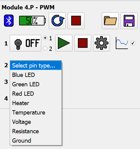
The available pin types are:
- Blue/Green/Red LED - Provides repeating pulse-rest waveforms for optogenitic stimulation.
- Blue, red, and green LED controls all function the same. The different color options are available to help distinguish fibers with multiple colors of LEDs.
- Heater - Provides a one-shot pulse for powering a heating element.
- Temperature - Provides NTC temperature recording.
- Voltage - Provides voltage application and recording.
- Resistance - Provides resistance recording.
- Ground - Does nothing but shows which pin on the fiber is allocated as ground.
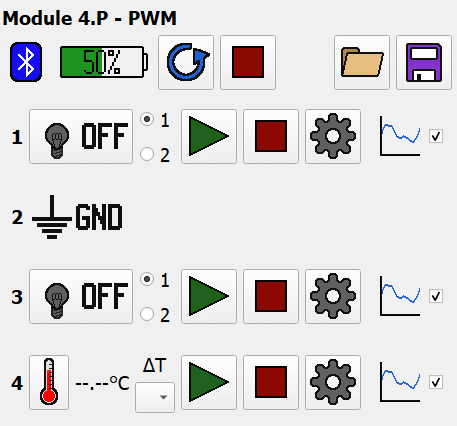
Here’s an example of a module that’s been set up with the following pin layout:
- Blue LED
- Ground
- Green LED
- Temperature
LED Pin
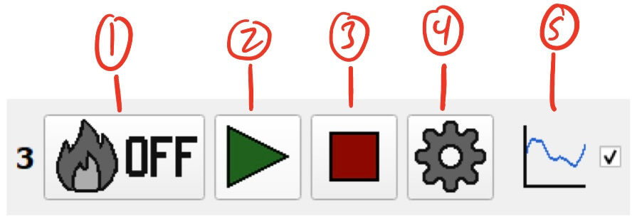
LED Pin Controller
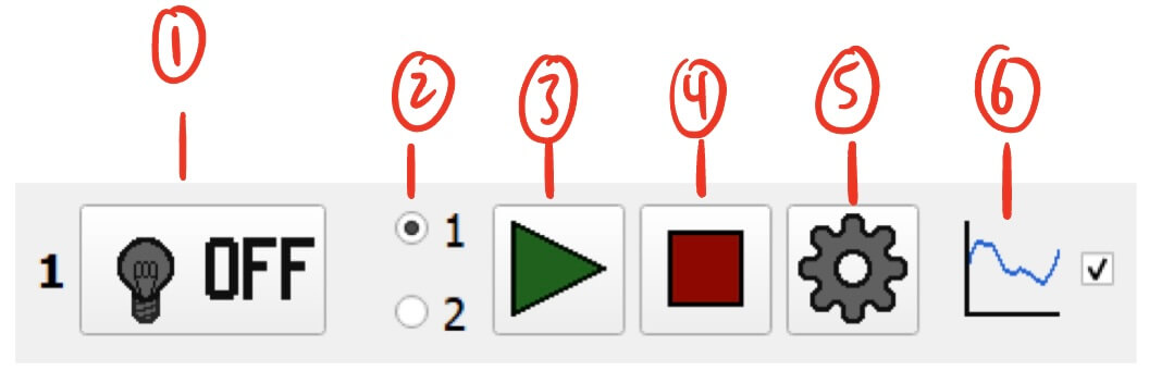
- LED Status and Manual Control Button - Displays LED status and allows for manual control.
- Clicking this button will toggle the LED pin on and off.
- The button will automatically update to reflect the status of the LED pin on the module. These statuses are:
- Off - LED is completely off

- On - LED is completely on (at the duty cycle/voltage set in the settings)

- Pulsing - LED is currently pulsing on and off (according to the waveform set in the settings)

- Resting - LED is currently off and resting (for a duration defined by the waveform set in the settings)

- Off - LED is completely off
- Pulse Selection Radio Buttons - Switch between two pulse waveforms as defined in the settings.
- This allows for quickly switching between two different waveforms.
- Start Button - Starts the current LED pulse waveform.
- Stop Button - Stops the current LED pulse waveform.
- Once stopped, the LED pin will turn off.
- Settings Button - Settings for the LED pin.
- Graph Display Toggle - Toggles the visibility of the LED pin on the module’s graph.
- This can help declutter the graph by hiding unnecessary data.
LED Pin Settings
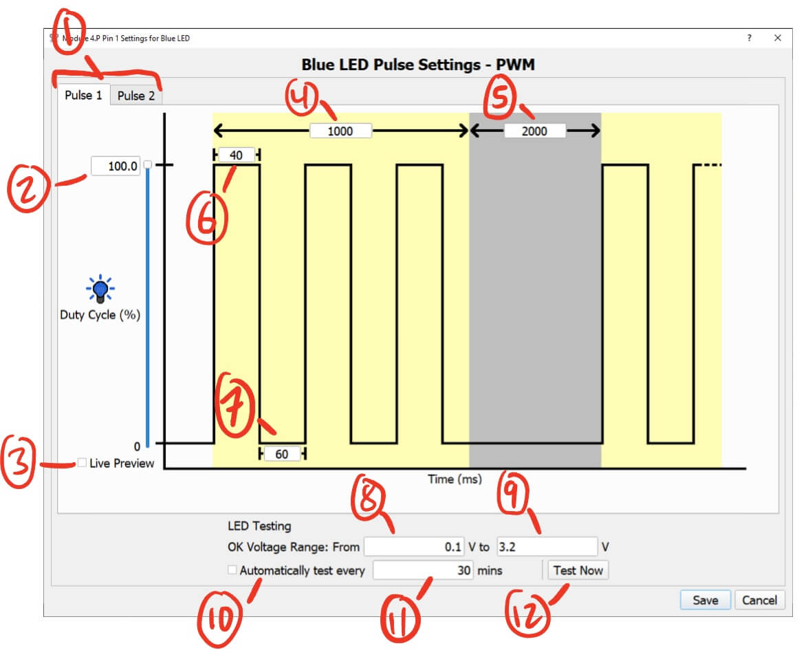
- Pulse 1/2 Selection - For configuring two different pulses.
- You can configure two LED pulse waveforms per pin. You can select which one is being applied using the
Pulse Selection Radio Buttonsin the LED Pin Controller.
- You can configure two LED pulse waveforms per pin. You can select which one is being applied using the
- LED Intensity - Sets the intensity of the LED.
- You can either enter a value manually or adjust it using the slider.
- The intensity is defined as follows:
- For PWM modules, it is the duty cycle for the LED and ranges from 0-100%. The voltage is always 3.3v.
- For Analog modules, it is the voltage applied to the LED and ranges from 0-3.3v.
- Live Preview - Checking this will turn on the LED pin at the current intensity.
- Changes to the intensity will be reflected on the LED pin in real time.
- Pulse Duration (ms) - The duration of the pulse waveform.
- Rest Duration (ms) - The duration of the rest between pulse waveforms.
- Pulse On Duration (ms) - The duration the LED pin is on before switching off during the pulse waveform.
- Pulse Off Duration (ms) - The duration the LED pin is off before switching on during the pulse waveform.
- LED Testing Lower Voltage (V) - The lower voltage bound for LED testing.
- A tested voltage lower than this bound indicates that there is a short in the circuit.
- LED Testing Upper Voltage (V) - The upper voltage bound for LED testing.
- A tested voltage higher than this bound indicates that there is a break in the circuit.
- Automatic LED Testing Checkbox - Check this to enable automatic testing.
- Automatic LED Testing Frequency (minutes) - The duration between automatic tests.
- Manual Test Button - Tests the LED pin for shorts or breaks.
- The test will measure the voltage drop across the LED.
- The expected result should be the forward voltage of the LED, but various factors can change that slightly. Therefore there is an acceptable range that can be defined to gauge whether a voltage registers as a short, break, or OK.
- Here is an example of an “OK” result from testing:
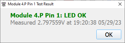
- Failed tests will report either a short or a break.
LED Pin Notes
- Do not set any of the Pulse/Rest durations to
0. This can cause the module to fail. - To achieve a waveform of just LED on and LED off (no resting) you can do the following:
- For the example of a repeating 1000ms on, 2000ms off waveform:
- Pulse Duration: 1000ms
- Rest Duration: 2000ms
- Pulse On Duration: 1100ms
- Pulse Off Duration: 100ms
- For the example of a repeating 1000ms on, 2000ms off waveform:
Heater Pin
Heater Pin Controller
- Heater Status and Manual Control Button - Displays Heater status and allows for manual control.
- Clicking this button will toggle the Heater pin on and off.
- The button will automatically update to reflect the status of the Heater pin on the module. These statuses are:
- Off - Heater is completely off

- On - Heater is completely on (at the duty cycle/voltage set in the settings)

- Pulsing - Heater is currently on and will turn off at the end of the pulse (as defined in the settings)

- Off - Heater is completely off
- Start Button - Starts the Heater pulse.
- Stop Button - Stops the Heater pulse.
- Once stopped, the Heater pin will turn off.
- Settings Button - Settings for the Heater pin.
- Graph Display Toggle - Toggles the visibility of the Heater pin on the module’s graph.
- This can help declutter the graph by hiding unnecessary data.
Heater Pin Settings
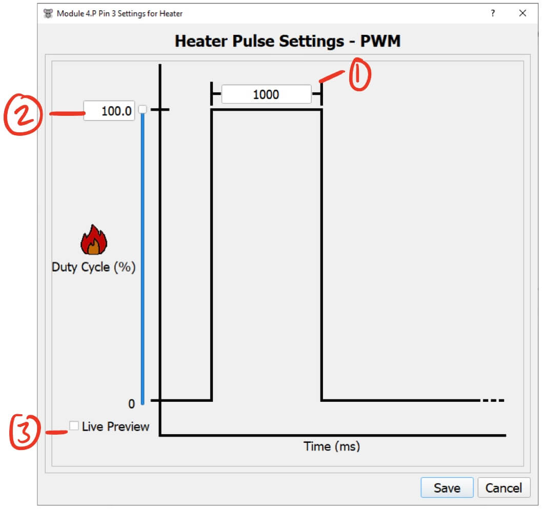
- Pulse Duration (ms) - The duration of the heater pulse before turning off.
- Heater Intensity - Sets the intensity of the Heater.
- You can either enter a value manually or adjust it using the slider.
- The intensity is defined as follows:
- For PWM modules, it is the duty cycle for the Heater and ranges from 0-100%. The voltage is always 3.3v.
- For Analog modules, it is the voltage applied to the Heater and ranges from 0-3.3v.
- Live Preview - Checking this will turn on the Heater pin at the current intensity.
- Changes to the intensity will be reflected on the Heater pin in real time.
Heater Pin Notes
- The Heater pulse will not repeat. If you want to have a repeating cycle, I recommend taking a look at Automations.
- Do not set the Pulse duration to
0. This can cause the module to fail.
Temperature Pin
Temperature Pin Controller
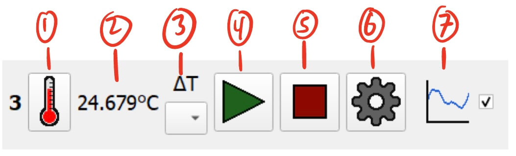
- Temperature Manual Reading Button - Allows for manual reading of the pin temperature.
- Clicking this button will request a temperature reading from the module.
- The manual reading will ignore the delta settings.
- Current Temperature Reading (°C) - Displays the last measured temperature reading from the pin.
- Delta Settings - Designates another pin on the module to measure the temperature delta between. See Temperature Pin Delta for more information.
- Start Button - Starts measuring temperature.
- Stop Button - Stops measuring temperature.
- Settings Button - Settings for the temperature pin.
- Graph Display Toggle - Toggles the visibility of the temperature pin on the module’s graph.
- This can help declutter the graph by hiding unnecessary data.
Temperature Pin Delta
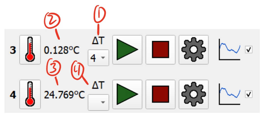
- Delta Pin Selection - On the primary pin, select the delta pin to compare.
- In this example, we use Pin 3 as the primary pin and select Pin 4 as the delta pin.
- Temperature Delta Display - Displays the temperature difference of the primary pin minus the delta pin.
- In this example, we are seeing:
Pin 3 temperature - Pin 4 temperatureon Pin 3’s display.
- In this example, we are seeing:
- Temperature Average Display - Displays the average temperature of the primary pin and the delta pin.
- In this example, we are seeing:
(Pin 3 temperature + Pin 4 temperature) / 2on Pin 4’s display.
- In this example, we are seeing:
- Other Delta Pin Selection - Do not select anything on the delta pin’s delta selection.
- In this example, we selected Pin 4 as the delta for Pin 3, so we select nothing for Pin 4.
- To start measuring the delta use the
Startbutton on the primary pin.- In this example, you would press
Starton Pin 3.
- In this example, you would press
Delta Notes:
- The delta and average are only for real time analysis. The recorded data will only include the raw temperature measured by each pin.
- Delta mode only sends one point per batch. Keep this in mind when setting the time between each sample.
- Be sure to synchronize the moving average in the settings on each pin.
Temperature Pin Settings
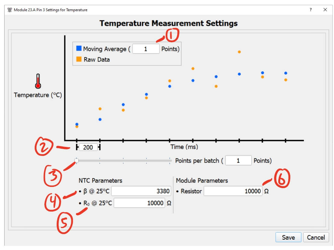
- Moving Average (points) - The number of points to include in the moving average.
- This helps filter noise and smooth out the data.
- Higher values will smooth the data more but will take longer to reflect changes in the temperature reading.
- Lower values will keep the data noisy but will quickly reflect changes in the temperature reading.
- I recommend a value of 5 to start with.
- Time between each sample (ms) - The time between each temperature measurement.
- Points per batch (points) - The number of points to combine in a single message from the module.
- The module measure data at the rate set by
Time between each sample, and oncePoints per batchpoints have been measured, the module sends all of them at once. - E.g. with 3
Points per batch, the module will collect 3 measurements then send them all at once. - See the Temperature Pin Notes for more details.
- The module measure data at the rate set by
- NTC Beta value @ 25°C - The fiber NTC’s measured beta value at 25°C.
- The data sheet for the NTC should have an approximation of this, but it’s important to measure this value for each NTC that you use to get accurate temperature calculations.
- NTC nominal resistance @ 25°C - The fiber NTC’s measured nominal resistance at 25°C.
- The data sheet for the NTC should have an approximation of this, but it’s important to measure this value for each NTC that you use to get accurate temperature calculations.
- Module Resistor Value (Ω) - The pin resistor used on this module.
- This resistance is specific to the pin configuration on each module.
Temperature Pin Notes
- Try to only send data from this pin every 200ms or so. You can send data faster than this, but it may prevent other data from being sent from the module. This is ok for temperature, but could mean that information from other pins (such as LED status) could get lost.
- For example, if you want to read temperature every 40ms, then increase the
Points per batchto 5 so that data is only sent after 5 points are measured, i.e. every 200ms. - When you are using delta mode, it will only send 1 point per batch regardless of the
Points per batchsetting.
- For example, if you want to read temperature every 40ms, then increase the
- It’s important to set up the NTC and Module parameters correctly to get accurate temperature measurements. If you don’t need super accurate data, then you can just use the NTC infromation from its corresponding data sheet.
Voltage Pin
Voltage Pin Controller
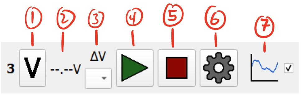
- Voltage Manual Reading Button - Allows for manual reading of the pin voltage.
- Clicking this button will request a voltage reading from the module.
- The manual reading will ignore the delta settings.
- Current Voltage Reading (V) - Displays the last measured voltage reading from the pin.
- Delta Settings - Designates another pin on the module to measure the voltage delta between. See Temperature Pin Delta for more information. (It’s the same for voltage.)
- Start Button - Starts measuring voltage.
- Stop Button - Stops measuring voltage.
- Settings Button - Settings for the voltage pin.
- Graph Display Toggle - Toggles the visibility of the voltage pin on the module’s graph.
- This can help declutter the graph by hiding unnecessary data.
Voltage Pin Settings
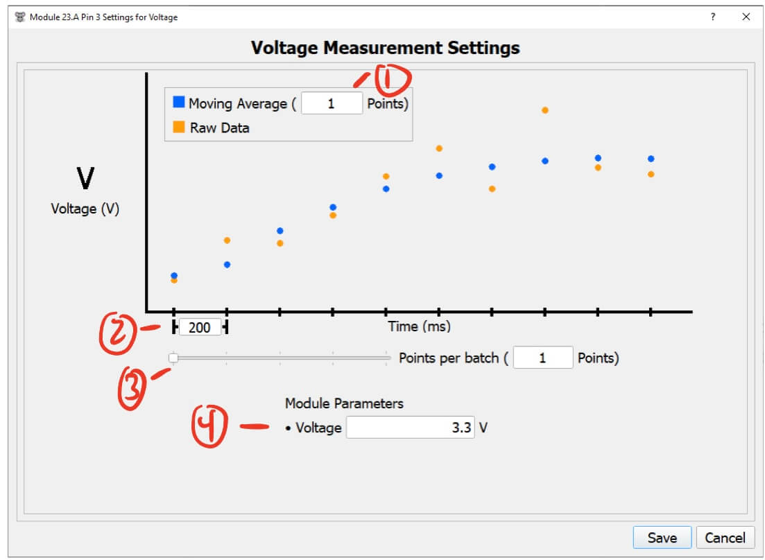
- Moving Average (points) - The number of points to include in the moving average.
- This helps filter noise and smooth out the data.
- Higher values will smooth the data more but will take longer to reflect changes in the voltage reading.
- Lower values will keep the data noisy but will quickly reflect changes in the voltage reading.
- I recommend a value of 5 to start with.
- Time between each sample (ms) - The time between each voltage measurement.
- Points per batch (points) - The number of points to combine in a single message from the module.
- The module measure data at the rate set by
Time between each sample, and oncePoints per batchpoints have been measured, the module sends all of them at once. - E.g. with 3
Points per batch, the module will collect 3 measurements then send them all at once. - See the Voltage Pin Notes for more details.
- On PWM modules this value is fixed at 3.3v, but Analog modules can set this value from 0-3.3v
- The module measure data at the rate set by
Voltage Pin Notes
- Try to only send data from this pin every 200ms or so. You can send data faster than this, but it may prevent other data from being sent from the module. This is ok for voltage, but could mean that information from other pins (such as LED status) could get lost.
- For example, if you want to read voltage every 40ms, then increase the
Points per batchto 5 so that data is only sent after 5 points are measured, i.e. every 200ms. - When you are using delta mode, it will only send 1 point per batch regardless of the
Points per batchsetting.
- For example, if you want to read voltage every 40ms, then increase the
Resistance Pin
Resistance Pin Controller
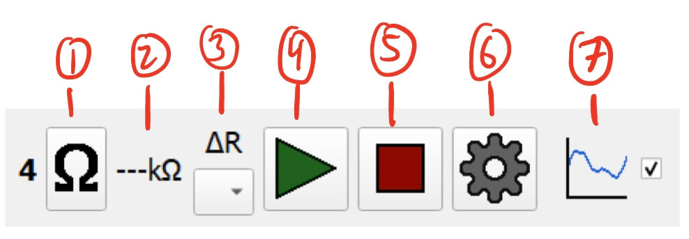
- Resistance Manual Reading Button - Allows for manual reading of the pin resistance.
- Clicking this button will request a resistance reading from the module.
- The manual reading will ignore the delta settings.
- Current Resistance Reading (kΩ) - Displays the last measured resistance reading from the pin.
- Delta Settings - Designates another pin on the module to measure the resistance delta between. See Temperature Pin Delta for more information. (It’s the same for resistance.)
- Start Button - Starts measuring resistance.
- Stop Button - Stops measuring resistance.
- Settings Button - Settings for the resistance pin.
- Graph Display Toggle - Toggles the visibility of the resistance pin on the module’s graph.
- This can help declutter the graph by hiding unnecessary data.
Resistance Pin Settings
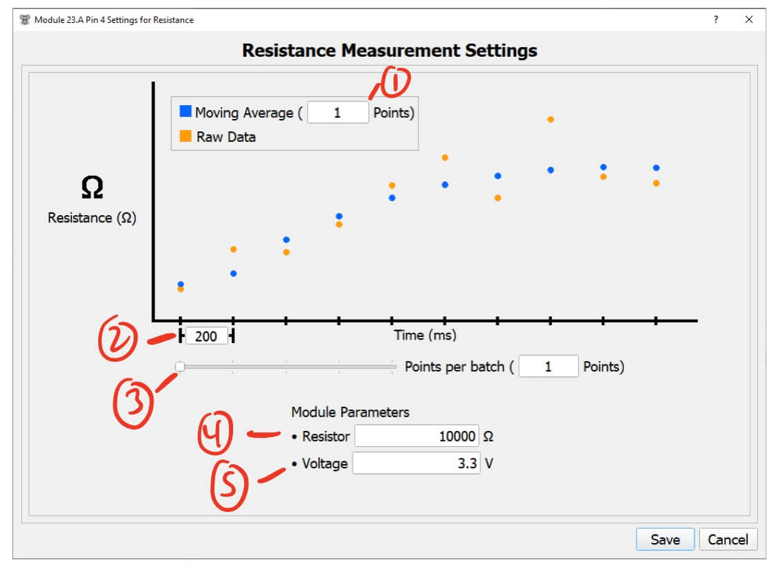
- Moving Average (points) - The number of points to include in the moving average.
- This helps filter noise and smooth out the data.
- Higher values will smooth the data more but will take longer to reflect changes in the resistance reading.
- Lower values will keep the data noisy but will quickly reflect changes in the resistance reading.
- I recommend a value of 5 to start with.
- Time between each sample (ms) - The time between each reistance measurement.
- Points per batch (points) - The number of points to combine in a single message from the module.
- The module measure data at the rate set by
Time between each sample, and oncePoints per batchpoints have been measured, the module sends all of them at once. - E.g. with 3
Points per batch, the module will collect 3 measurements then send them all at once. - See the Resistance Pin Notes for more details.
- The module measure data at the rate set by
- Module Resistor Value (Ω) - The pin resistor used on this module.
- This resistance is specific to the pin configuration on each module.
- Output Voltage (V) - The voltage to apply when taking a measurement.
- On PWM modules this value is fixed at 3.3v, but Analog modules can set this value from 0-3.3v.
Resistance Pin Notes
- Try to only send data from this pin every 200ms or so. You can send data faster than this, but it may prevent other data from being sent from the module. This is ok for resistance, but could mean that information from other pins (such as LED status) could get lost.
- For example, if you want to read resistance every 40ms, then increase the
Points per batchto 5 so that data is only sent after 5 points are measured, i.e. every 200ms. - When you are using delta mode, it will only send 1 point per batch regardless of the
Points per batchsetting.
- For example, if you want to read resistance every 40ms, then increase the
Ground Pin
Does nothing but shows which pin on the fiber is allocated as ground.