Modules - Charger
Quick Links
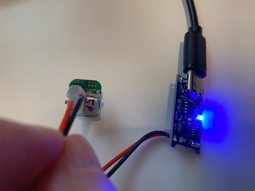
Using the charger
- Plug the charging board into the USB-C power supply.
- You may need to press a button on the power supply cable to turn it on.
- The board should show a solid blue LED
- Plug the charger into the module.
- Connect
B+on the charging board toBon the module - Connect
B-on the charging board to-on the module
- Connect
- Wait for the module to charge.
- While the module is charging, you will see the red LED light up.
- The blue LED may also be lit during charging.
- When the module is done charging, you will only see the blue LED.
- This takes about 10-15 minutes.
- You can leave the module on the charger without worrying about over-charging; it stops when the battery is full.
- While the module is charging, you will see the red LED light up.
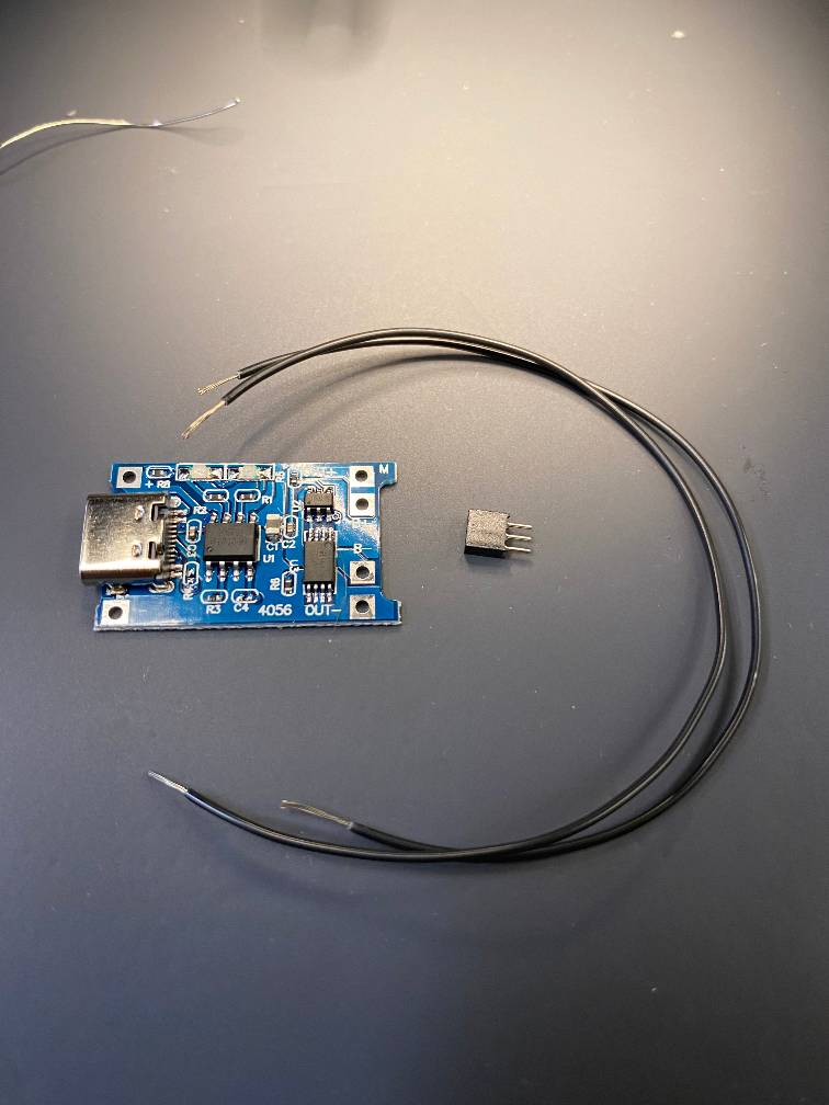
What you’ll need:
- Battery charging board
- USB-C Power supply
- Solder
- Soldering iron
- Wires
- Female 3-pin header
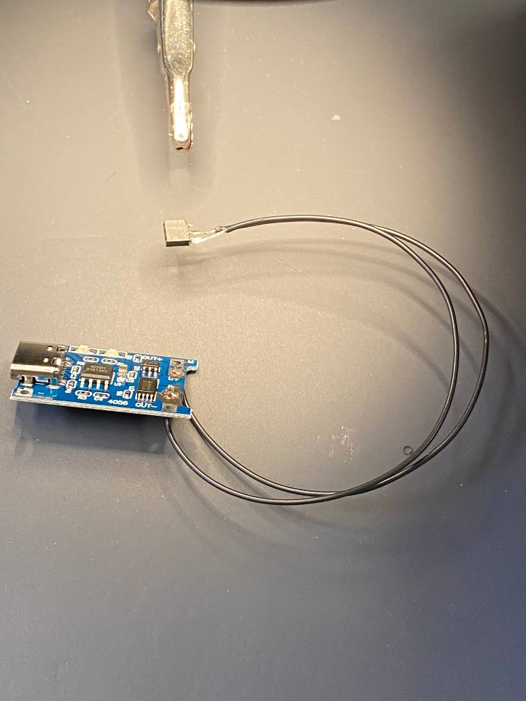
Creating the charger
1. Prepare the components
The 3-pin female header should fit on the power header pins of a module.
I recommend using different color wires for + and -, but I didn’t have them available when I made this charger.
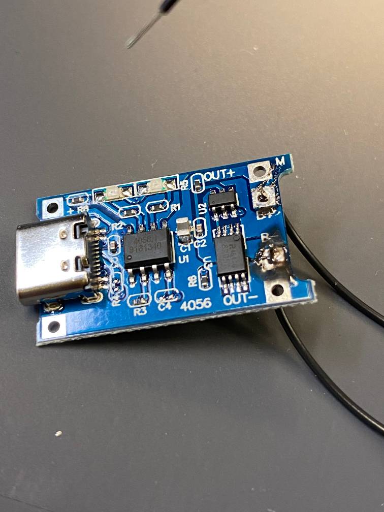
2. Solder the charging board
Solder one end of the wires to the B+ and B- terminals. I recommend using a red wire for B+ and a black for B-
3. Remove a pin from the edge of the header
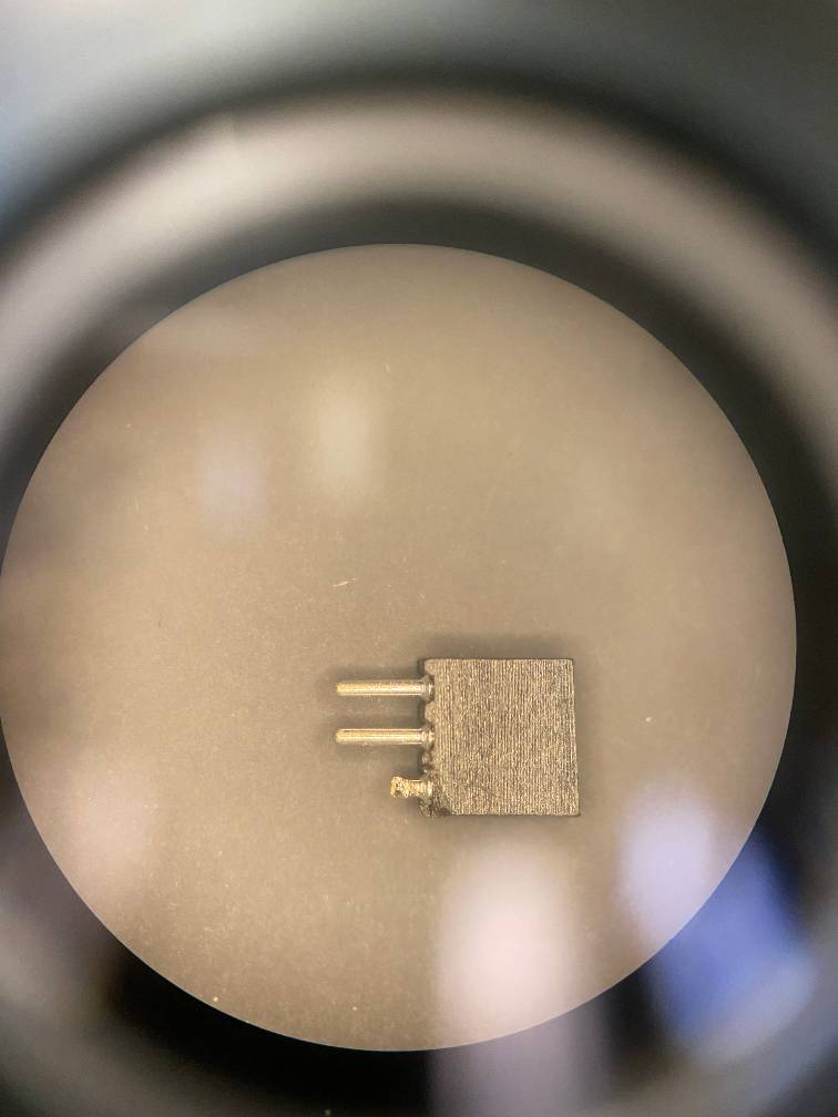
4. Solder the other end of the wires to the header
Connect the B+ wire to the middle pin.
Connect the B- wire to the outer pin.
5. Secure the wires
Using some epoxy or hot glue, secure the wires so that the exposed bits don’t cross, and the wires don’t get ripped out.