Modules - Configuration
Quick Links
- What you’ll need
- Reconfiguring old modules
- Configuring a PWM module
- Configuring an Analog module
- Choosing header pins
What you’ll need:
- An assembled module
- Resistors and headers for the module
- Solder paste
- Heat gun
- Tweezers
- (optional) Sewing needle
- This helps me apply small amounts of solder paste evenly
Reconfiguring old modules
Have a pre-configured module, but want to change the configuration? Just remove the components, and put on new ones!
If the module already has a battery, remove that before reconfiguring. Heat gun + battery = fire.
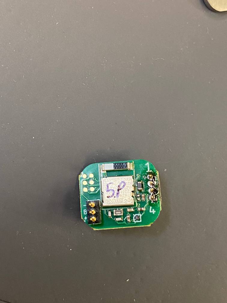
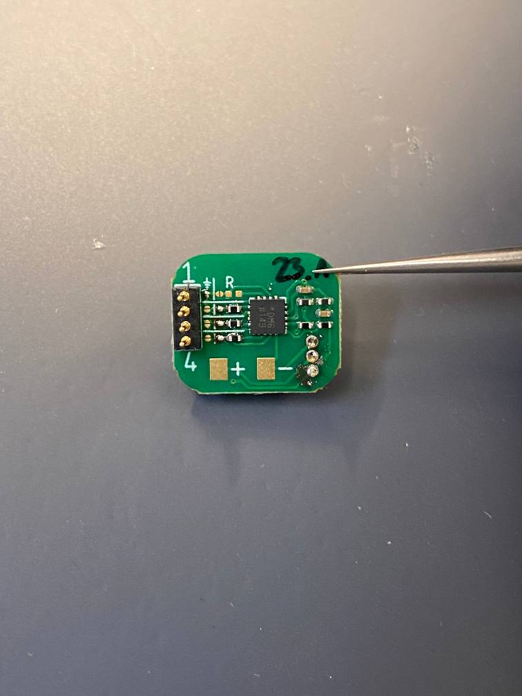
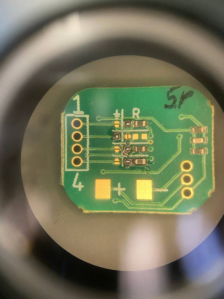
Configuring a PWM module
The PWM module has simpler circuitry on the back, but the structure of the resistor configuration is the same. See Fiber Circuits for more information.
I’m going to configure this module with the following configuration:
| Pin | Fiber Component | Ground Jumper | Resistor Jumper | Resistor |
|---|---|---|---|---|
| 1 | Blue LED | Soldered | 0 Ohms | |
| 2 | Ground | Soldered | ||
| 3 | Green LED | Soldered | 0 Ohms | |
| 4 | 10k Ohm NTC | Soldered | 10k Ohms |
1. Prepare the resistor circuit
The first pin on the fiber is going to be an LED pin. So I’m going to add solder paste to the resistor jumper and the resistor pads.
I’ll put on a 0 ohm resistor using tweezers for the LED pin.
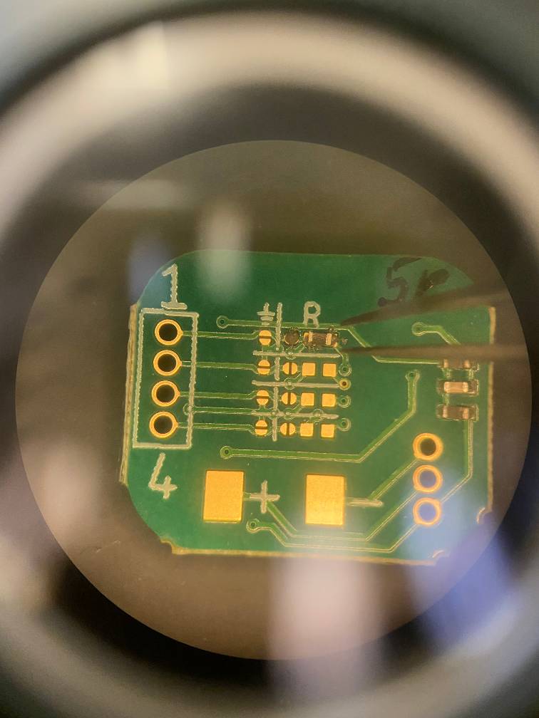
The second pin on the fiber is ground, so I’ll add solder paste to the ground jumper.
I’ll go ahead and set up the rest of the components.
2. Solder the components
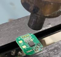
Using a heat gun, I’ll melt the solder paste and solder the components.
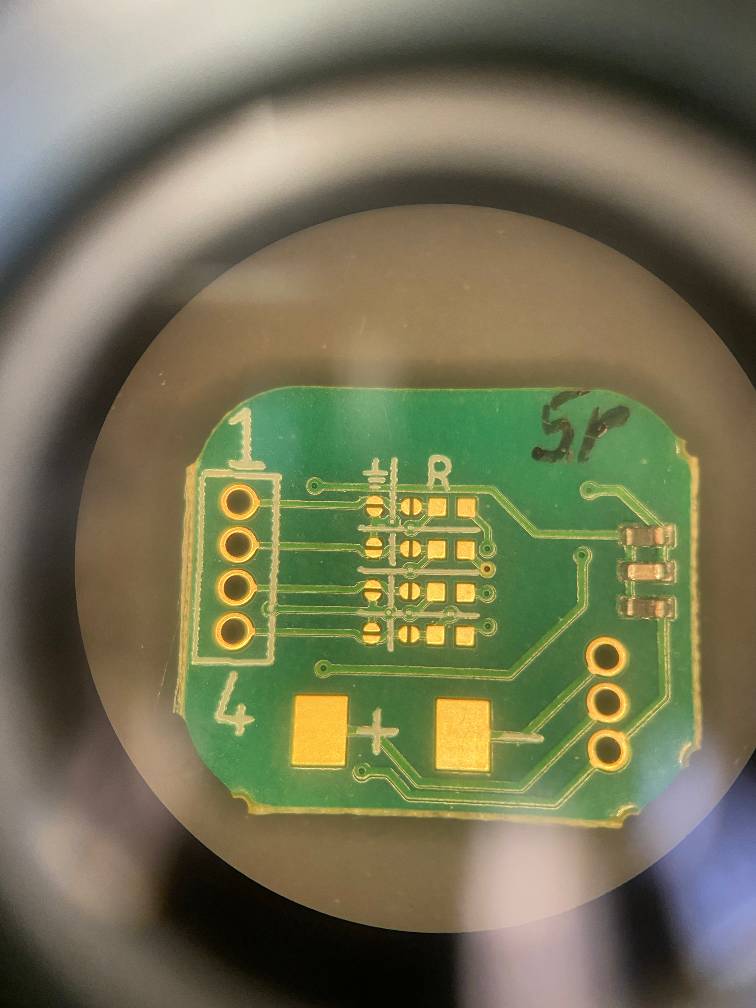
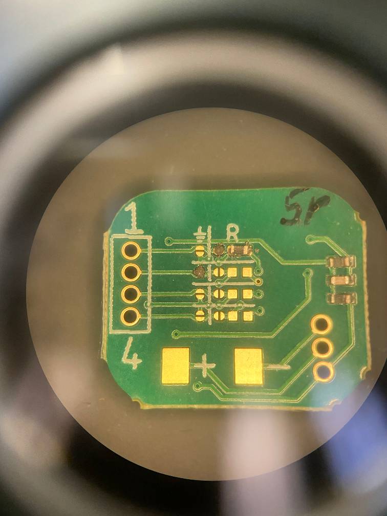
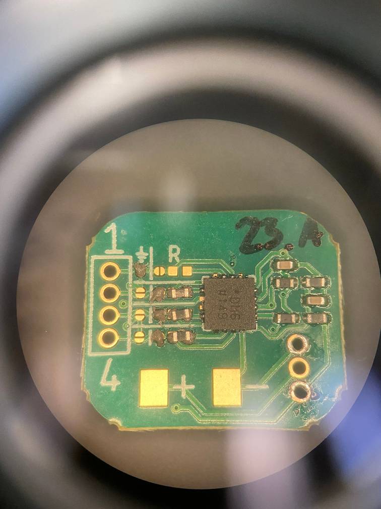
3. Inspect
Taking a look at this circuit, we can see a couple issues:
- None of the jumpers are connected. The two bumps mean the solder isn’t bridging. We can fix that by adding more solder and reheating.
- The bottom resistor fell off, so we’ll need to resolder that.

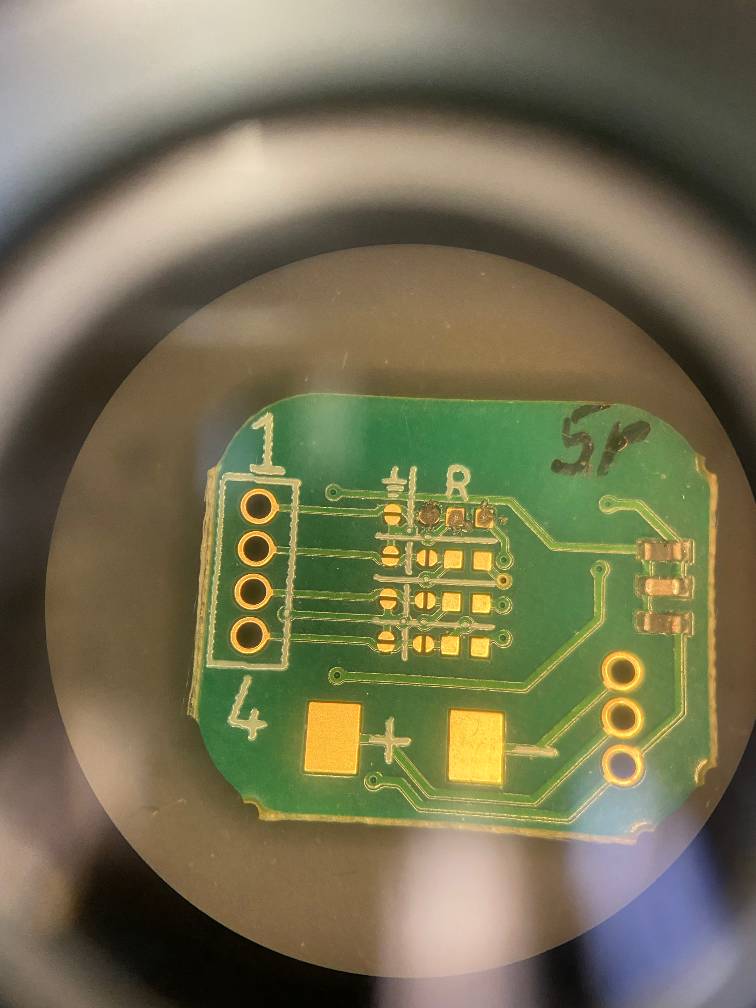
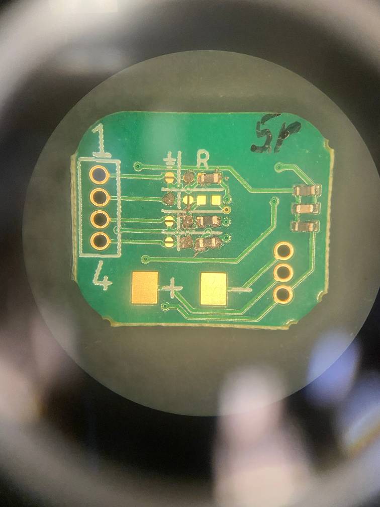
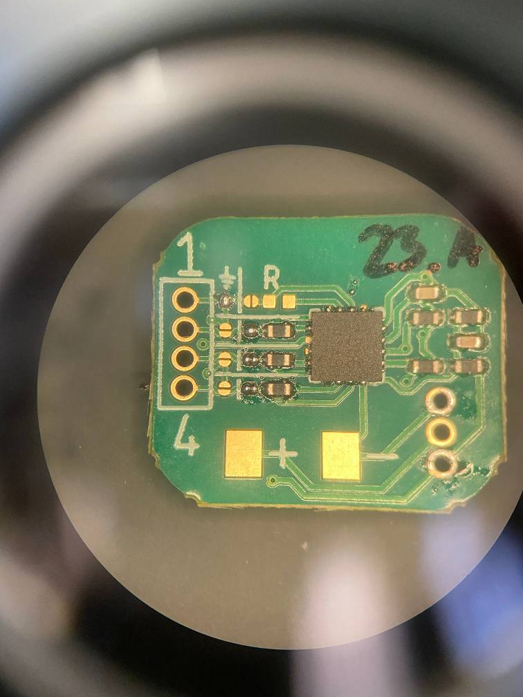
4. Fix issues and inspect
After fixing the issues, everything looks good! The solder is on solid mound on each of the jumpers; that’s exactly what we want to see.
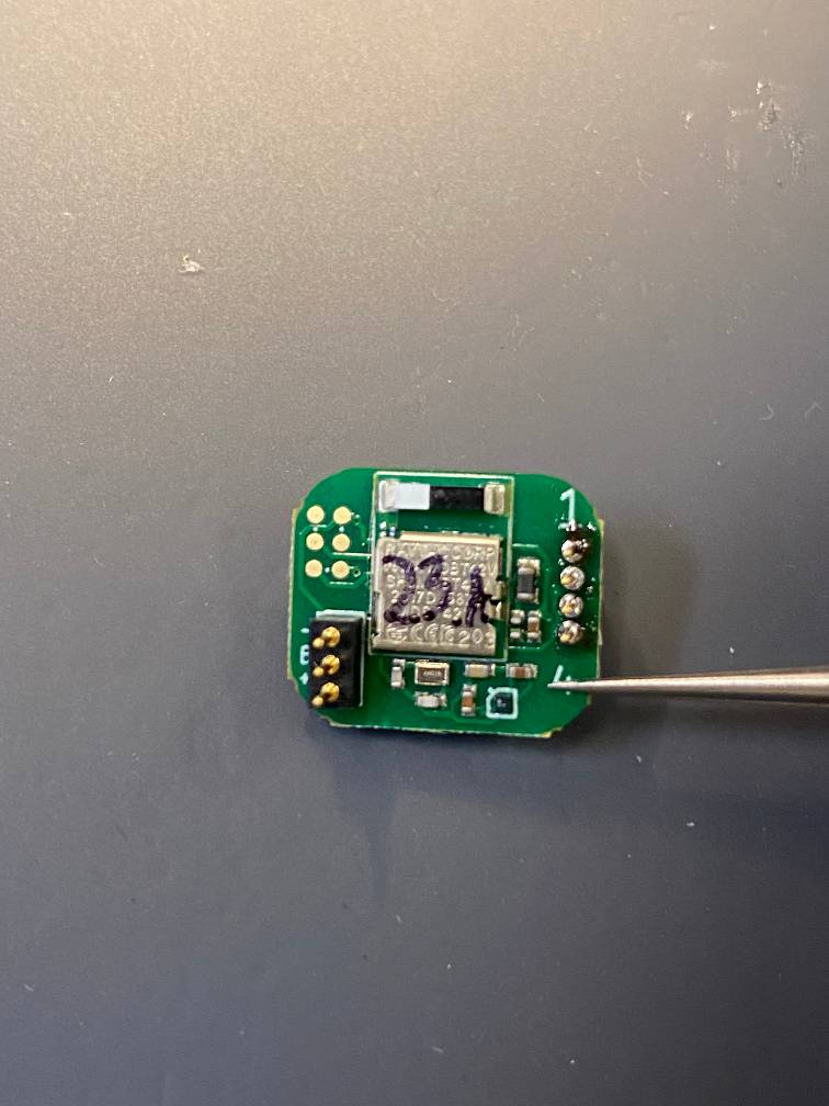
Configuring an Analog module
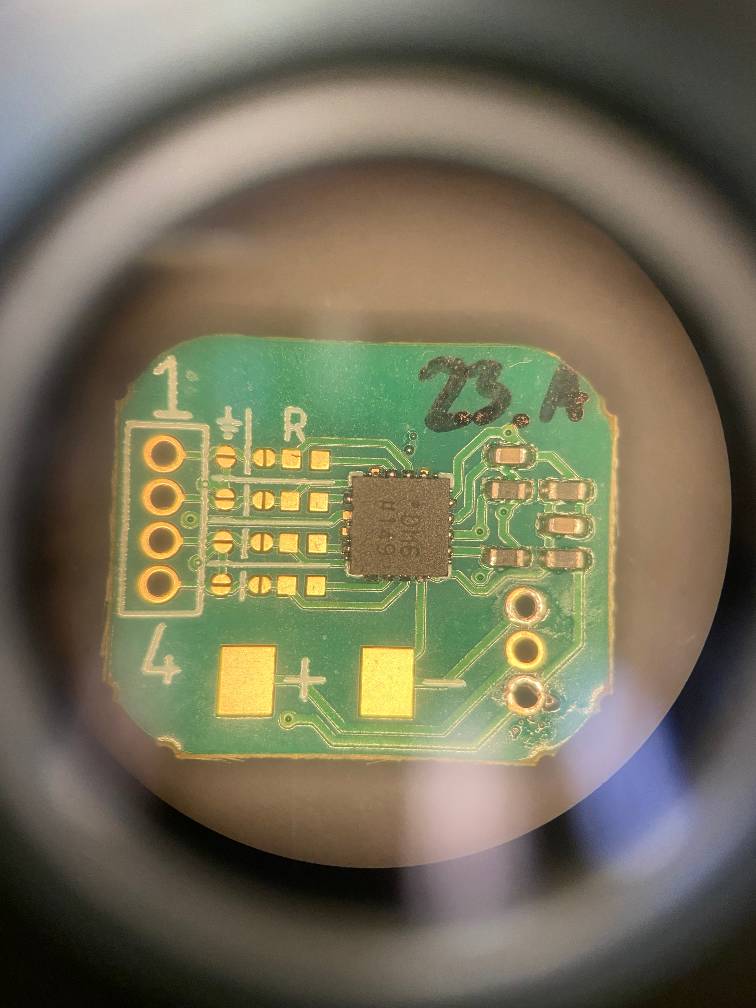
The Analog module has more complex circuitry on the back, but the structure of the resistor configuration is the same. See Fiber Circuits for more information.
I’m going to configure this module with the following configuration:
| Pin | Fiber Component | Ground Jumper | Resistor Jumper | Resistor |
|---|---|---|---|---|
| 1 | Ground | Soldered | ||
| 2 | Heater/Red LED | Soldered | 0 Ohms | |
| 3 | 10k Ohm NTC | Soldered | 10k Ohms | |
| 4 | 10k Ohm NTC | Soldered | 10k Ohms |
1. Prepare the resistor circuit
The first pin on the fiber is ground, so I’ll add solder paste to the ground jumper.
The second pin on the fiber is going to be a heater/LED. So I’m going to add solder paste to the resistor jumper and the resistor pads. I’ll also put on a 0 ohm resistor using tweezers for the LED pin.
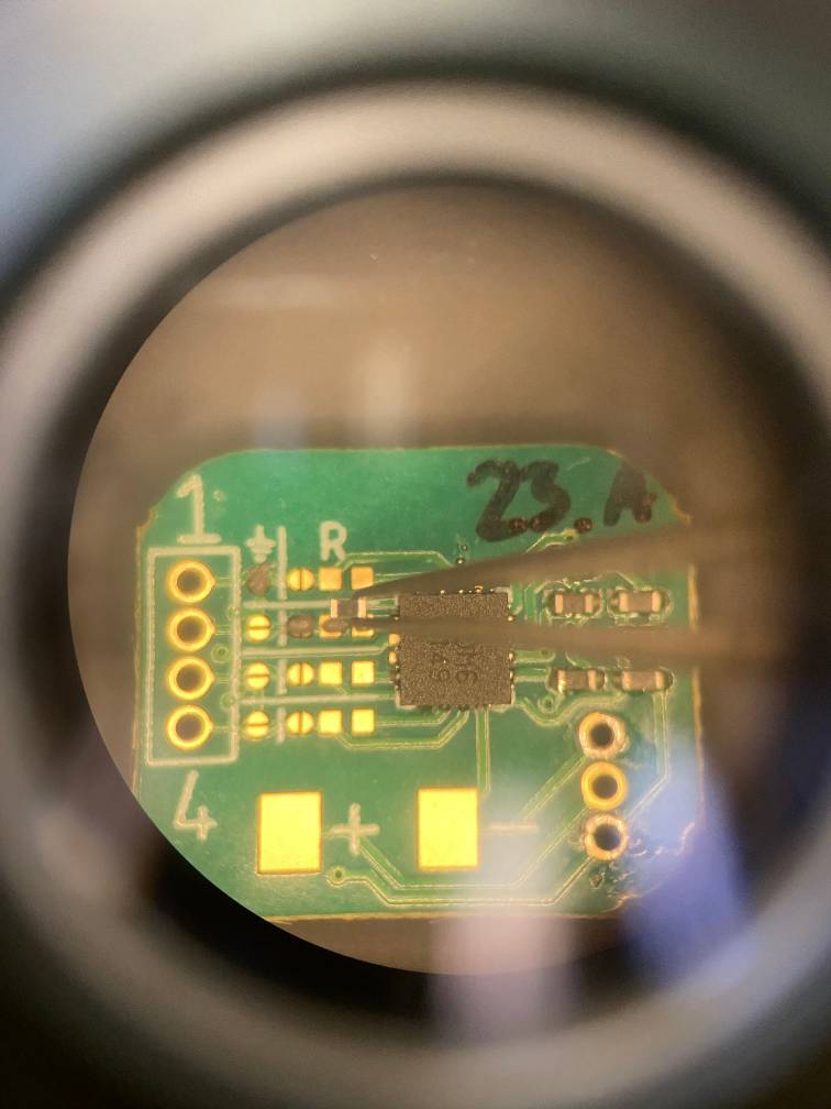
I’ll go ahead and set up the rest of the components.
2. Solder the components
Using a heat gun, I’ll melt the solder paste and solder the components.
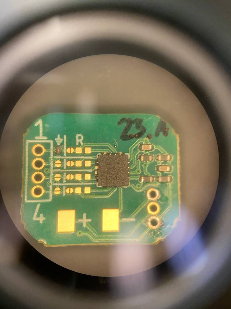
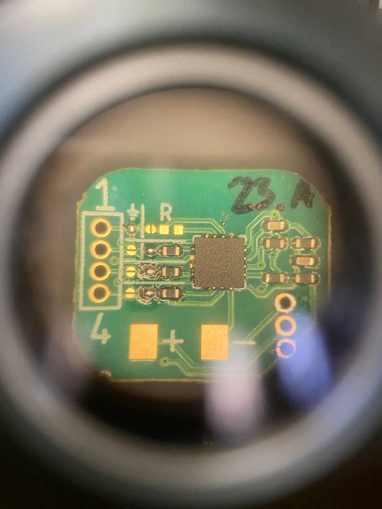
3. Inspect
Taking a look at this circuit, we can see a couple issues:
- The jumpers on pins 3 and 4 are not connected. The two bumps mean the solder isn’t bridging. We can fix that by adding more solder and reheating.
4. Fix issues and inspect
After fixing the issues, everything looks good! The solder is on solid mound on each of the jumpers; that’s exactly what we want to see.
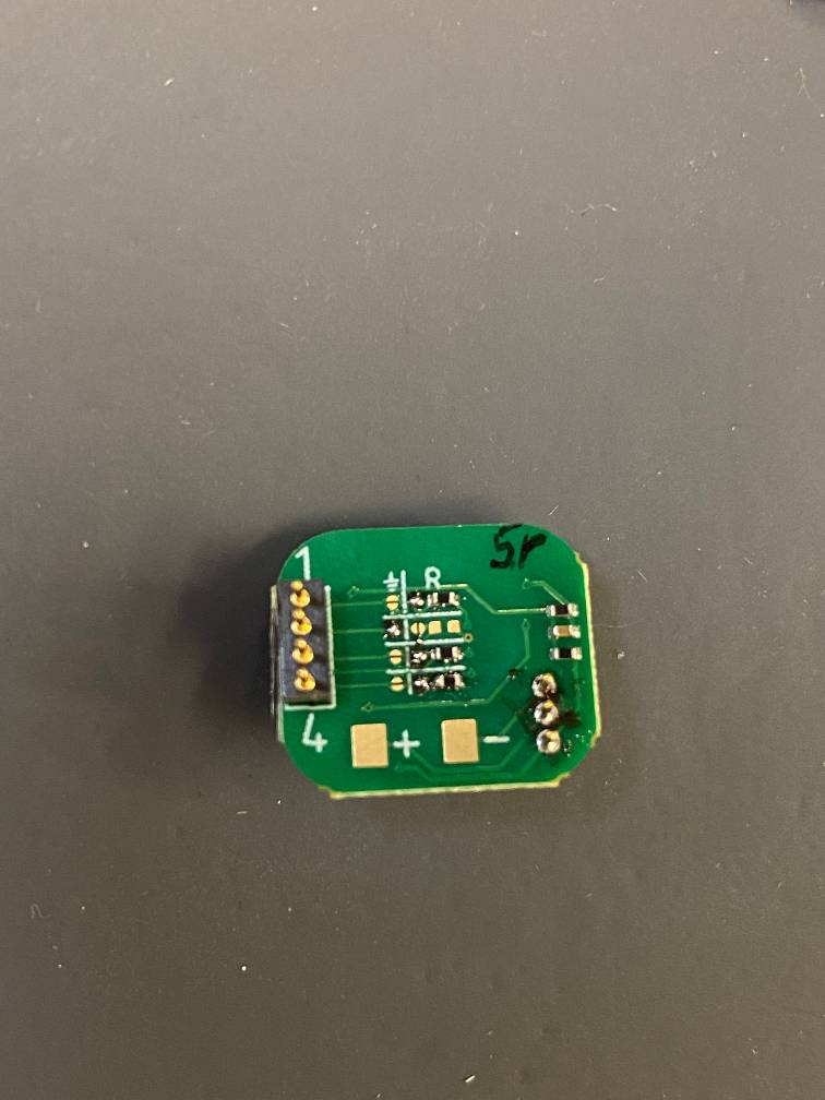
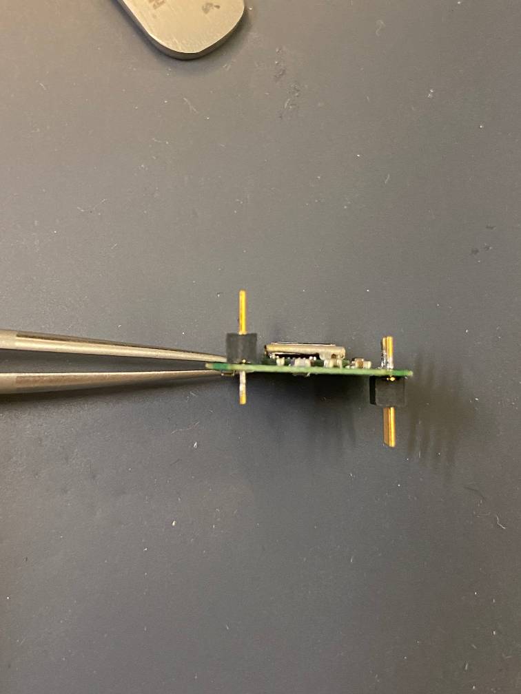
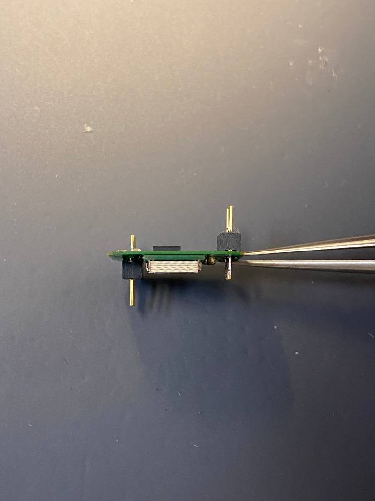
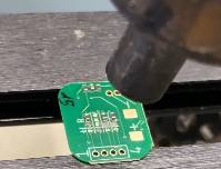
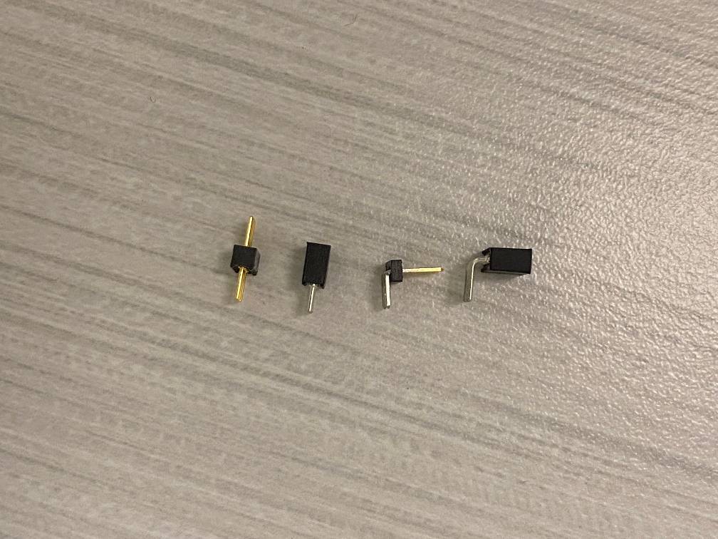
Choosing header pins
The most commonly used header pins are male header pins, such as in the picture below.
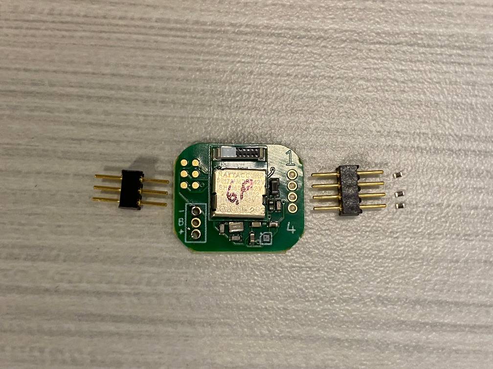
However, you can use whatever style of header pins best fits the needs of your project! Here are a few different styles for inspiration.
Here are the modules we configured above with header pins attached.