Modules - Programming
Quick Links
- What you’ll need
- 1. Set up the environment
- 2. Modify the firmware
- 3. Set up the hardware
- 4. Program the module
- 5. Testing the module
What you’ll need:
- Hardware:
- A blue dev board with a jtag programming attachment
- You may want to remove/bend away the guiding pins
- A power supply for the modules, anywhere from 3.3-5V. Unfortunately batteries don’t supply enough current so you’ll have to use a wired power supply.
- An assembled module (doesn’t need to be configured)
- A blue dev board with a jtag programming attachment
- Software:
- The Arduino IDE
- The Adafruit NRF52 Bluefruit library
- Adalink
- It requires the python command to map to Python3 so you may need a virtual environment in order to make it work.
- J-Link
- The Neuromodular github repo (only available to lab members)
1. Set up the environment
Install everything in the software section above.
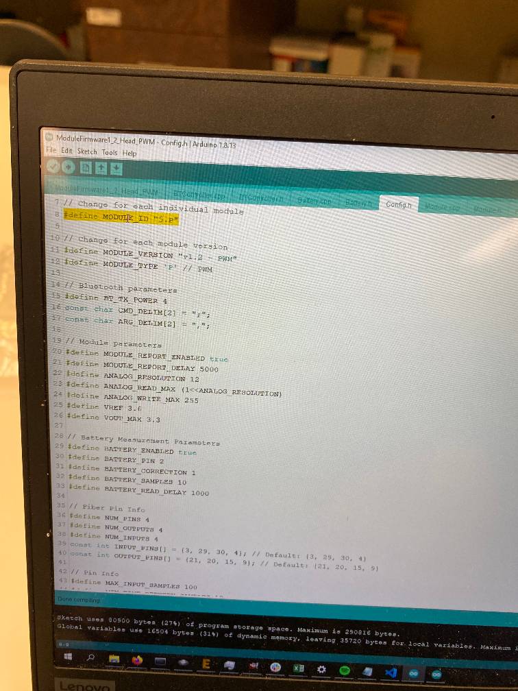
2. Modify the firmware
Make any changes you need to the code in ModuleFirmware/, then increment the MODULE_ID in Config.h.
Compile the firmware:
- In the Arduino IDE, under
Tools->BoardselectAdafruit Feather nRF52832 - Use
Sketch->Export compiled Binaryto generate the .hex binary file for the firmware.
3. Set up the hardware
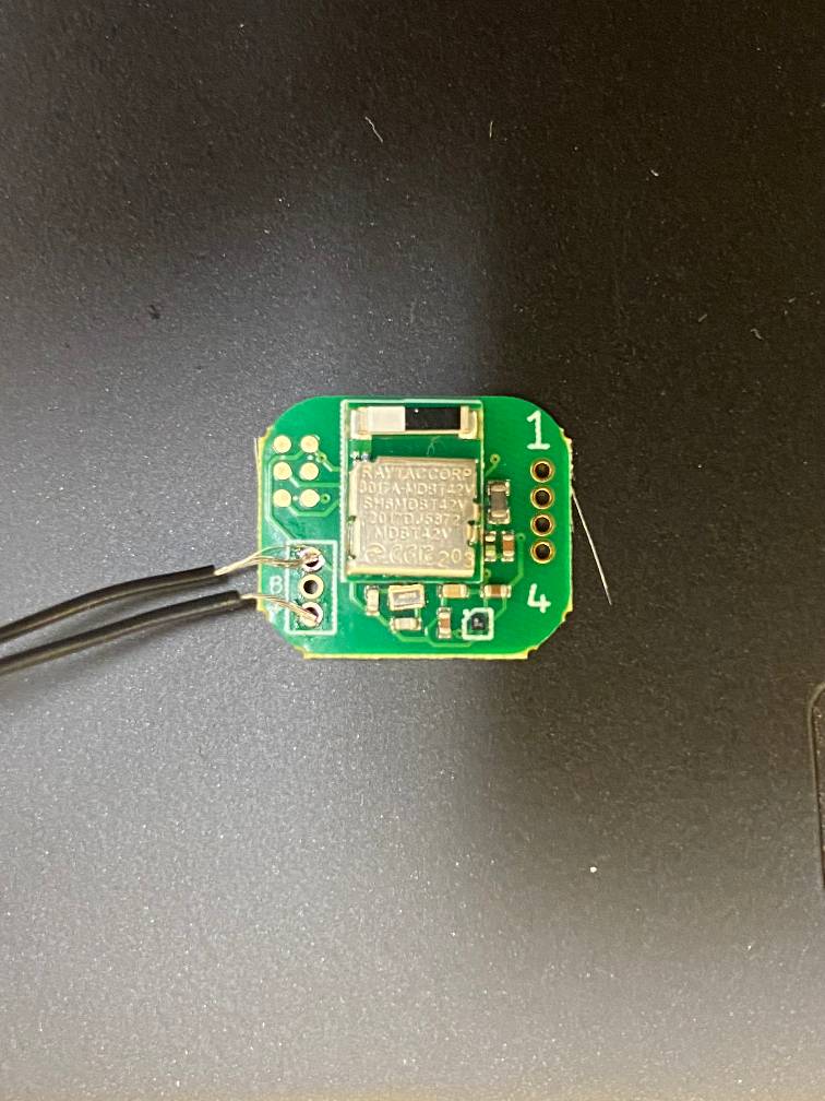
First, hook up the module to a power supply running anywhere from 3.3V to 5V.
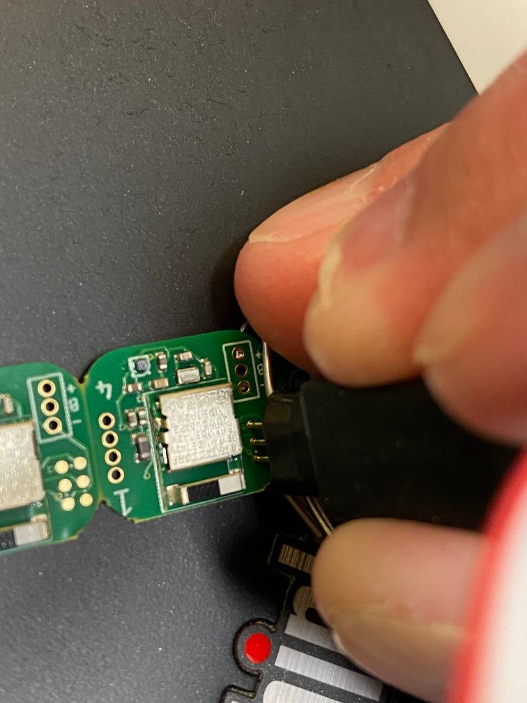
When programming unconfigured modules, I made a USB power cable and soldered the wires to the + and - power pins on the module:
Plug in the jtag connector and plug the blue dev board into your computer
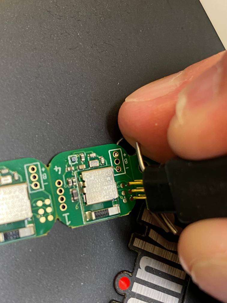
4. Program the module
During programming, you’ll need to hold the jtag connector firmly against the jtag pins on the module. It’s pretty tricky to both hold the connector and type in commands on the command line, so I recommend having the commands ready to be copied or already entered in to the command line so that you can just press the up/down arrows and the enter key.
- In the python environment you set up,
cdto theNeuromodularrepo root directory - While holding the jtag connector to the jtag pins on the module, run the following commands:
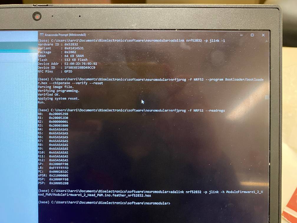
adalink nrf52832 -p jlink -i- In the output, you’ll want to see
Hardware ID : 0x52832 - If you see
Hardware ID : 0x52840instead, it’s not registering the module but instead reading the dev board. Try readjusting the jtag and make sure the module is getting power.
- In the output, you’ll want to see
nrfjprog -f NRF52 --program Bootloader/bootloader.hex --chiperase --verify --reset- This will take a while, so you will have to hold the jtag in place securely for the entire duration.
- You should see
Parsing image file.->Verifying programming.->Verified OK.->Applying system reset.->Run. - If a module has already been flashed with the bootloader, you don’t need to do it again.
nrfjprog -f NRF52 --readregs- If the bootloader was flashed correctly, you should see a bunch of registers (R4-R2) report the value
0xA5A5A5A5
- If the bootloader was flashed correctly, you should see a bunch of registers (R4-R2) report the value
adalink nrf52832 -p jlink -h module/firmware/path/module_firmware_file.ino.feather_nrf52832.hex- Replace
module/firmware/path/module_firmware_file.ino.feather_nrf52832.hexwith the firmware file you’re trying to upload. - If you’re in the root directory, these are the paths to the generated hex files:
ModuleFirmware/ModuleFirmware1_2_Head_Analog/ModuleFirmware1_2_Head_Analog.ino.feather_nrf52832.hexModuleFirmware/ModuleFirmware1_2_Head_PWM/ModuleFirmware1_2_Head_PWM.ino.feather_nrf52832.hex
- Replace
Here is the output for a successful programming process:
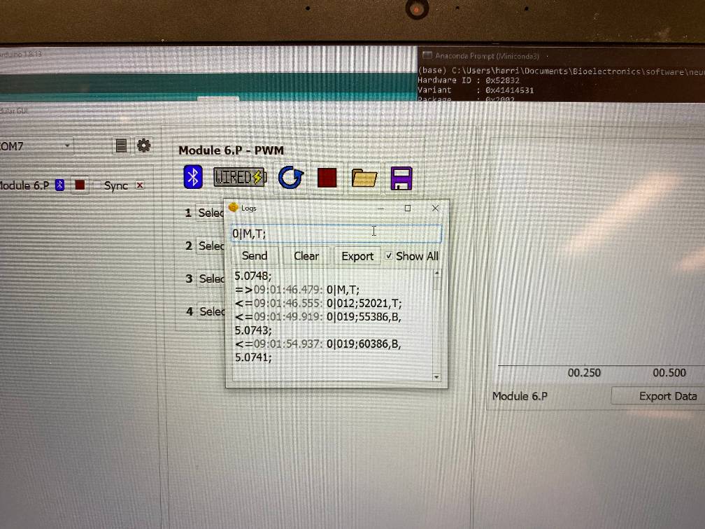
5. Testing the module
You can see if the module is working by using the GUI. The module should appear like normal, and you can check the logs to see if any data is coming through from the module.